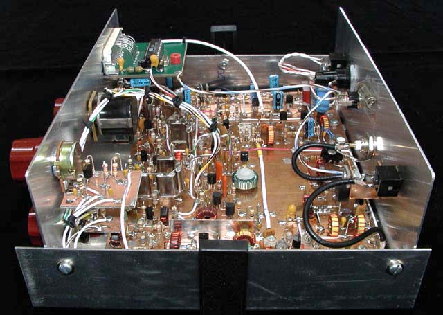
Follow down this page to see how this rig was constructed!
The 5 X 7 inch substrate
is partitioned off as shown. In general, each stage is built within the
defined areas.
Construction on this rig started with the receiver T/R switch which is also part of the front-end gain control system.
The parts for the gain control function were added when the control for that capability was built and installed.
Next, the receive input bandpass filter parts were added. Polystyrene capacitors were used as those were available in the junk box. Any NPO disc ceramic or monolithic ceramic capacitor could be used here also.
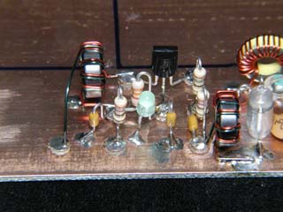
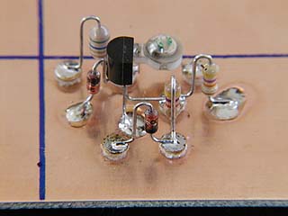
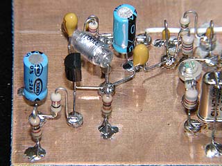
This is the first version of the receive RF amplifier, which was a conventional, grounded base configuration. It was later abandoned after determining it produced excessive noise and replaced with a Norton "noiseless feedback" amplifier. That amplifier configuration is shown in the next picture.
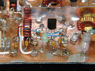
Surprisingly (and fortuitously), all of the pads that were needed for the above amplifier configuration were also needed for the Norton design shown here. That made rebuilding this stage very easy. In fact, a number of parts were of the same value and were retained in their original positions.
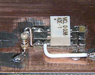
A MiniCircuits ADE-1 level 7 mixer was soldered to its own substrate, and that in turn glued to the main substrate. Connections to the mixer were then added.
Note: Minicircuits is discouraging the purchase of this mixer in small quantities by charging a very high price for one or two units. An alternative is to purchase the SCM-1 mixer that is essentially identical in performance and about one-third the cost of an ADE-1.
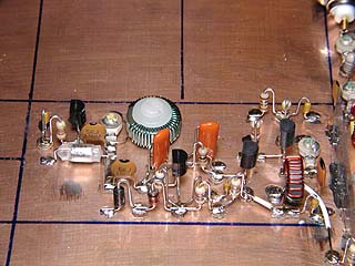
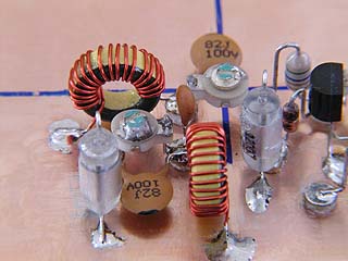
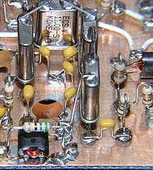
The VFO circuitry was added next, so that the front-end of the receiver could be tested. The VFO main inductor (green wire) is mounted to the substrate with a pair of #8 nylon shouldered washers and a 4-40 nylon screw.
Installed between the VFO and the RF amplifier is a shield made from thin, tin plated steel stock obtained at a hobby shop.

Next, the receive post-mixer amplifier components were added. This stage took additional development time to get it matched to the crystal filter correctly.
After the post-mixer amplifier was working correctly, the 4-pole main crystal filter was added. The crystal cases are grounded to maximize performance, and that also adds mechanical stability to the elements. The binocular core in the foreground is the input transformer to the IF amplifier stage.
The receive IF amplifier uses two transistors in a common base-common emitter configuration. MPSH10 transistors were required to achieve the desired stage gain of 40 dB. PN2222 transistors were tried, but those ran out of gas well before the desired gain was achieved.
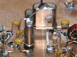
After the IF amplifier, two crystals and their associated components were added to complete the roofing filter. Again, the crystal elements were grounded. The 33 Ohm resistor used to terminate this filter can be seen to the far left.
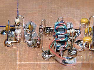
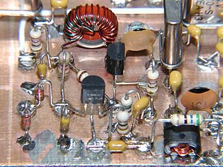
Components to create the product detector were next added. The trifilar transformer was wound using kynar insulated wire wrap wire in three colors, readily available at Radio Shack and many other sources. It's a bit slippery to handle, but works well overall. The unterminated lead in the foreground will be connected to the local oscillator output in the next step.

Next, the receive local oscillator was built. The lead from the product detector above is now attached to the output low pass filter of this stage.
With an outboard audio amplifier connected to the output of the product detector, the receiver could be used to listen to signals on 20 meters.
Completing the build along the front edge of the board is the receive audio preamplifier stage. The large 3300 pF polystyrene capacitor in the middle of this image could be replaced with a much smaller mylar or monolithic ceramic capacitor. It was used because it was available.

At 90 degrees clockwise from the previous picture, the receive audio mute components were added. Missing is this image are the two germanium diodes which limit the audio level reaching this stage. Those were added later.
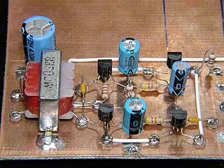
Completing the build along the short side of the substrate and also the completion of the receive strip are the components of the two-stage main audio amplifier.
This stage can drive earphones or a speaker to volume levels far above those needed for comfortable listening.
The volume control potentiometer will be connected to the rightmost pad shown in this image.
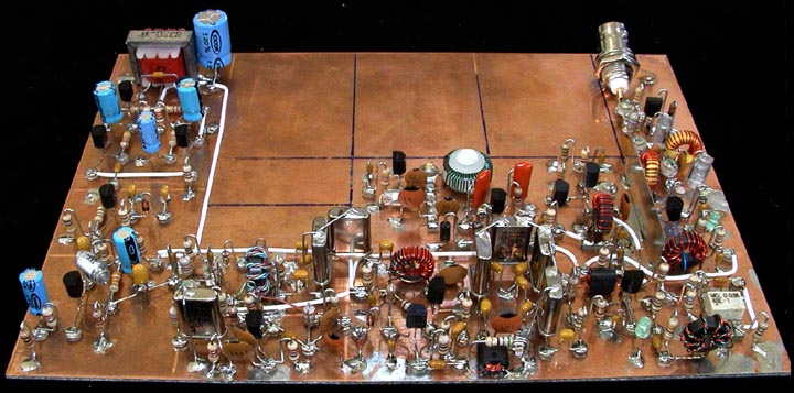
Completed receiver before rebuilding the receive RF amplifier.
Back to the "2N2/20" page