| Back to the "2N2/40+" page
|
| 2N2/40+ Schematic Diagrams |
|
|
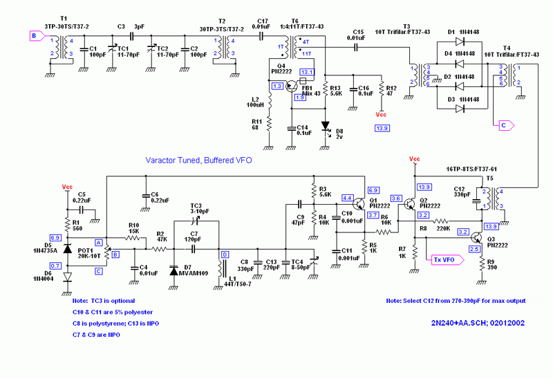
| This first schematic shows the rig from the receiver input through the first mixer, including the VFO section. Capacitor C12 could also be comprised of a fixed value in parallel with a suitable trimmer so that the output stage can be more easily peaked. |
|
|
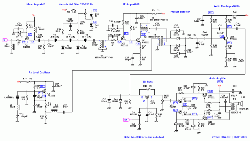
| This second schematic is basically the remainder of the receiver portion of the rig, except for the RIT circuitry is that is desired. |
|
|
| This schematic is essentially all of the transmit circuitry. The three 2N2222A transistors in the final could be replaced with a single RF transistor such as a 2SC2166, 2SC2078, or somthing similar for more output power. Three 2N2222A transistors will easily run 2 watts. |
|
|
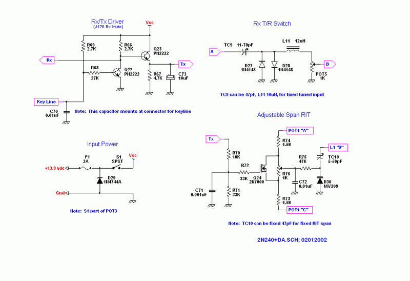
| The remaining schematic shows the remaining circuitry that is needed, except for the RIT. Receiver Incremental Tuning can be left out if it isn't desired. I like it for working DX and Foxes. |
|
|
|
|
Back to the "2N2/40+" page
|


