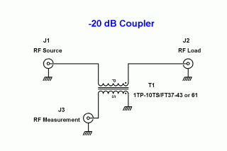
This is the basic schematic of a -20 dB coupler. The RF source is connected to the left port, a suitable load to the right port, and the measurement instrument input to the bottom port. The RF source might be the output stage of a QRP transmitter and the load, a 50 ohm dummy load. If the input impeance of the measurement instrument is 50 ohms, that input impedance is reflected back to the 1 turn transformer primary and looks like 0.5 ohms in series with the RF load.
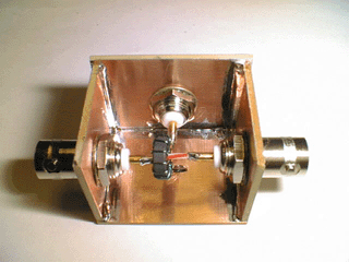
Shown is a more traditional implementation of the above circuit. The case is constructed from PC board material, and three coaxial connectors are used. The toroid transformer has a single turn going through it, which is the primary, and 10 turns are wound around the core, forming the secondary. One end of the secondary leads feeds the third coaxial connector, and the other lead is grounded to the case. This is the measurement port. Either of the other two ports can be used for the RF source or RF load.
A thin brass cover closes out the case on the finished coupler.
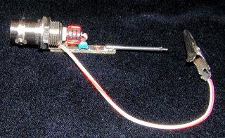
Here is an implementation of the coupler configured as a high impedance probe. The 50 ohm input impedance of the measurement instrument is in series with the 1-turn primary, and is reflected to the 10 turn secondary as 5000 ohms. This allows the low impedance instrument to be used to measure circuit performance without unduly loading that circuit and changing its performance.
Three FT25-43 cores are used, wound with 10 turns of #28 wire, and slipped over the center pin of the coax connector. A piece of wire from the center pin to ground complete the primary circuit. One of the secondary leads is grounded, and the other connects to the probe point through a small (blue object) 0.01 uF capacitor. A small piece of PC board material comprises the substrate upon which the parts are mounted.
Back to "Test Equipment" page