
Construction on this SW30+ began with the components for the coupled resonator receive band pass filter. Those are shown in this image. This is the upper left area of the PC board substrate.
As with most builds, the receiver will occupy one area of the substrate, the transmitter a second area, and common sections like power supplies and VFO a third area.

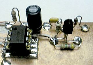
Before the NE602 mixer
stage could be built, a small substrate for the IC socket was fabricated.
One was used for each IC.
|
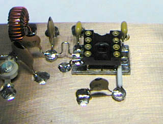
The 8-pin IC socket
was soldered to its substrate, that assembly glued to the main substrate,
and the remaining components added.
|
Below the mixer, the VFO components were added. This section is common to the receiver and transmitter, so is located between those two functional strips.
Adjacent and to the left of the VFO the beginnings of the power supply section was constructed. 8-volts was now available to operate the completed VFO and mixer stages.
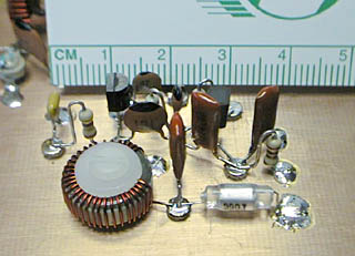
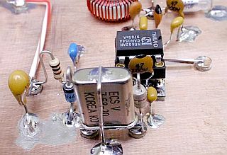
The 4-pole crystal filter was added next, followed by some of the product detector components. The substrate then looked as shown in this image.

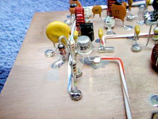
The remaining product detector components were next added and some of the parts for the audio preamplifier IC. The preamplifier frequency shaping and limiting components are connected between the long, parallel pads in the foreground.
Components for the receive mute were then placed, followed by the remaining components for the 2nd preamplifier stage. Those components are not show in this image.
With the basic receive strip done, the transmit mixer stage was added.
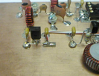
To power the transmit mixer stage, the T/R keying components were added. This stage supplies power to all of the transmit strip stages except the final amplifier.
The large yellow disc object in the left center area of this image is a solid state fuse.

Following the transmit mixer is another double tuned bandpass filter, almost identical to the receive input bandpass filter. This filter drives the first of two RF amplifier stages.

This is the second of the two RF amplifiers. The secondary of the transformer in the upper right of this image drives the final amplifier stage.
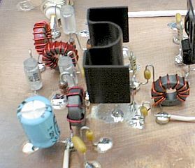
Looking from the opposite direction we see the final amplifier transistor, a 2SC799 with heatsink, and the output filter components. A heatsink has been added to the 2nd RF amplifier transistor to keep it cool also.
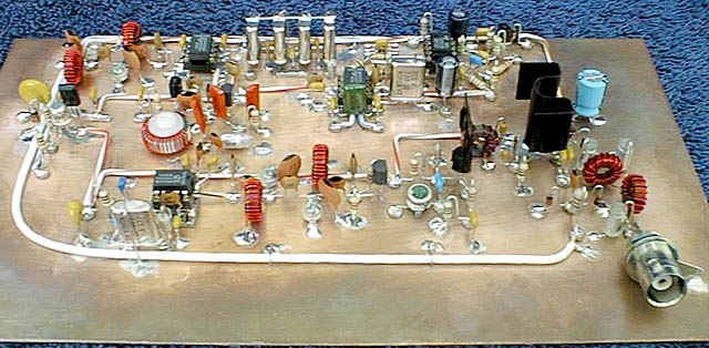
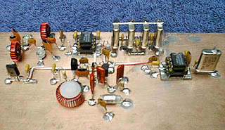
This is the almost completed
substrate. The coax connector was unsoldered and the excess substrate material
was removed prior to packaging the rig.
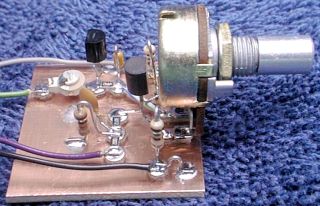
RIT module used in the rig. |
"Islander Amplifier" module used in the rig. |
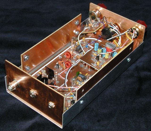
Completed SW30+ in case showing RIT and "Islander Amplifier" module locations.
Back to "SW30+" page